Turns gravity pipe runs into finished profile sheets in one command: detects every branch-free run, then per run creates the alignment through its structures, samples EG + FG surface profiles, builds the profile view, draws the run's parts into it, and labels them.
Pipe runs / created objects
Surface profiles / ticked runs
Labels & cautions
Bands / grid
What it does
- Run detection: interior structures never split a run (bends at manholes are normal); at a junction the two pipes closest to collinear (≤ 45° deflection) continue as one run, the trunk keeps going past a lateral tee, and every pipe lands in exactly one run.
- Per run: alignment through the structure centers (siteless, name de-duplicated) → EG/FG profiles via
CreateFromSurface(dynamic, they track the surface) → profile view with your style + band set → parts drawn in the view → pipe + structure profile labels. - Station 0 = downstream end (lower invert) by default, how pipe profiles are conventionally read; flip to upstream in the dialog.
- Stacking: views place from your picked top-left point, stepping down by measured height + gap, wrapping to a new column.
Settings & options
- Name template (
{network} {n} {first} {last}), alignment style / label set / layer, EG + FG surfaces (blank skips), profile + view styles, band set, pipe/structure label styles, all editable drop-downs. - Reference alignment toggle (on): the run alignment becomes each part's reference so station labels read correctly, the by-hand VDCPIPEREF step, folded in.
- Settings persist at
%APPDATA%\VDC\PipeViews\settings.json(overrideVDC_PIPEVIEWS_SETTINGS). - Pairs with:
VDCPROFXINGto pull crossing utilities into the new views;VDCPIPELABELfor crossing callouts;VDCPIPETABLEfor the schedules.
Dialog
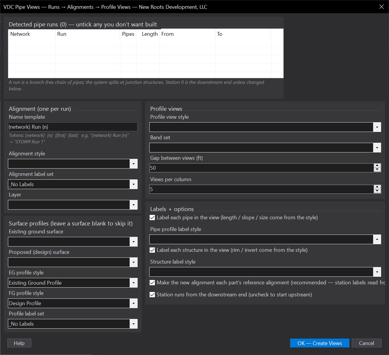
VDCPIPEVIEWSWhen to use it
- A utility plan is drawn and the plan-and-profile sheets are next - the create-alignment / create-view / sample-profiles / draw-parts / label chain is the alternative, per run.
- After an imported or converted network lands in the drawing and nothing has profile views yet.
- Re-cutting profile views after a major re-route: pick just the changed runs.
How to run it
- Run VDCPIPEVIEWS - the dialog lists every detected run (network, name, pipe count, length, end structures), all ticked. Untick what you don't want.
- Pick the alignment style/label set/layer, the EG + FG surfaces (leave one blank to skip that profile), profile + view styles, band set, and the label styles.
- OK, then pick the TOP-LEFT insertion point - views stack downward with your gap and wrap to a new column.
- Read the summary (alignments / views / profiles / parts / labels + any per-run notes). Undo reverses everything.
Options
- Name template: tokens {network} {n} {first} {last} - e.g. '{network} Run {n}' names 'STORM Run 1'; names de-duplicate against existing alignments.
- Reference alignment: on by default - each part's reference alignment becomes the new run alignment so station-based labels read correctly.
- Station direction: downstream-first by default (station 0 at the lower invert end); untick to start upstream.
- Stacking: gap between views (default 50 ft) and views per column (default 5) control the layout from the picked point.
Watch out for
- Gravity networks only in this version - pressure networks are skipped (crossings in the new views are VDCPROFXING's job).
- Leave both surfaces blank and the views are created with no profiles - parts still draw, but the elevation bands have no source.
- Curved pipes are chorded structure-to-structure in the alignment - fine for labels, not a survey-grade centerline.
- A run that fails (rare - e.g. an unresolvable name) lands in the summary notes; the rest of the batch continues.
Related: Profile Pipe Crossings QC · Pipe Ref · Pipe Crossing Labels · Pipe Table