VDCFLCONNECT is part of FL from Points (elevations from COGO points); the full section follows.
The field crew shot the grade breaks; the linework is still flat. VDCFLFROMPTS selects lines, polylines, and feature lines and gives every vertex the elevation of the COGO point sitting on it (nearest within a set tolerance): and anything that isn't a feature line becomes one. VDCFLCONNECT goes the other direction: pick COGO points in order (or type number ranges) and build one feature line through them at their elevations.
What it does
- Takes lines, arcs, polylines (2D/heavy/3D), and feature lines, window or pick a batch in one selection. Non-feature-lines are converted (siteless, source layer kept, source erased per settings).
- Vertex matching: nearest COGO point within the tolerance (default 0.50 ft, plan distance). Ties break to the lower point number, so reruns are deterministic.
- Mid-segment shots (on a straight segment, not near a vertex) become FL elevation points at their projection, carrying the point's elevation.
- Unmatched vertices: interpolate along the line between matched vertices (open ends carry the nearest matched elevation; closed loops wrap), or keep the existing elevation, your choice.
- Point scope: all points, one point group, or one layer (dropdowns list only what exists).
- No-op safe: a line with zero matched vertices is never converted, never saved, counted and reported instead.
- CSV report per run, every vertex: matched point #, distance, action, elevation, in the VDC Reports folder.
Workflow, VDCFLFROMPTS
- Type
VDCFLFROMPTS(VDC Civil » Feature Lines » FL from Points). - Set the point scope, tolerance, unmatched-vertex policy, and output options. OK.
- Select the linework, window, crossing, or picks. ENTER.
- Read the summary: converted / updated / untouched, matched vs interpolated vertices, elevation points added.
Workflow, VDCFLCONNECT
- Type
VDCFLCONNECT, choose open or closed. OK. - Pick COGO points in order; N adds a number range (
101-110,115), U un-picks. ENTER builds the feature line.
Settings
%APPDATA%\VDC\FlFromPoints\settings.json(envVDC_FLFROMPTS_SETTINGS). Tolerance, scope, policies persist.- Civil 3D's own
'PO/'PNtransparent commands trace points by hand inside Create Feature Line, these commands are the batch/dialog version.
Dialog

VDCFLFROMPTS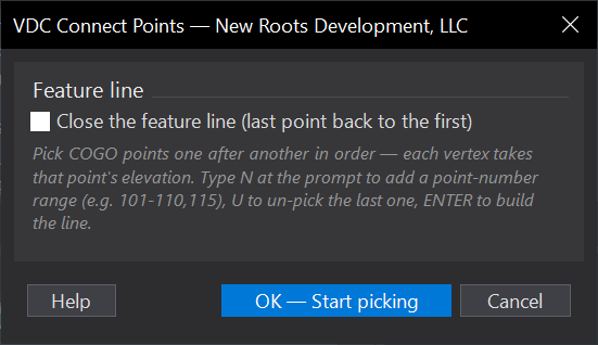
VDCFLCONNECTWhen to use it
- The field crew shot the grade breaks and the linework is still flat - EOP, swale, ditch, or curb lines traced or received at elevation zero.
- As-built or existing-features drafting: turn located linework plus its shots into 3D feature lines for surface building.
- Any time the alternative is tracing vertex-by-vertex with the 'PO transparent command.
How to run it
- Run VDCFLFROMPTS - set the point scope (all / one point group / one layer), the match tolerance, the unmatched-vertex policy, and the output options. Click OK.
- Select the linework - window, crossing, or picks, one selection. Press ENTER.
- Read the summary: converted / updated-in-place / untouched counts, the vertex funnel (matched, interpolated, carried, kept), elevation points added, and the report path.
Options
- COGO points to match: all points, one point group, or one layer - the dropdowns list only groups and layers that actually exist.
- Match a point within (ft): the vertex-match radius, plan distance (default 0.50). Ties break to the lower point number, so a rerun makes the same choices.
- Mid-segment elevation points: shots on a straight segment (not near a vertex) become FL elevation points at their projection, carrying the shot's elevation.
- Vertices with no nearby point: interpolate along the line between matched vertices, or keep the existing elevation.
- Erase the original line: on by default - the feature line replaces the source. Turn off to keep both.
- CSV report: every vertex with its matched point number, distance, action, and final elevation - in the VDC Reports folder.
Watch out for
- A line where NO vertex finds a point is left completely untouched - never converted, never saved - and counted with its reason. Check the tolerance and point scope if everything comes back untouched.
- Mid-segment matching skips arc segments - a projection onto the chord would not lie on the line. The count of rejected inserts in the summary is usually this.
- Xref linework cannot be converted (it belongs to the referenced drawing) - copy it into the host first.
- Converted feature lines get a PTS <handle> name (Civil 3D requires drawing-wide unique FL names).
Related: Connect Points · Feature Line Elevation Points · FL Delete Points